


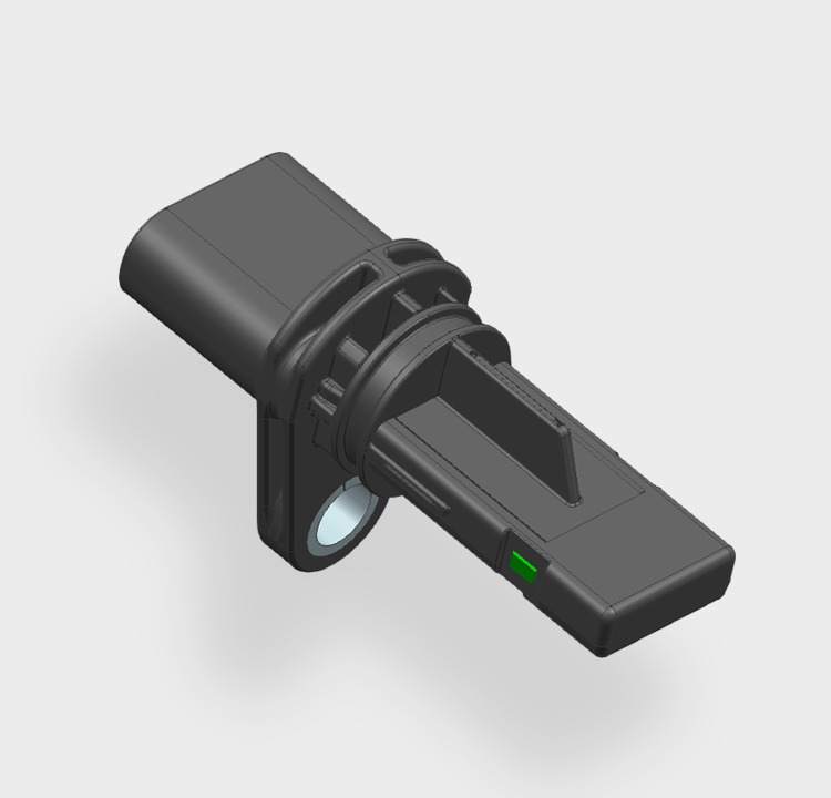
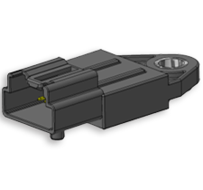
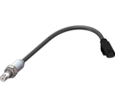
The product is designed based on Hall principle, and is installed on the chassis of the car. It is a sensor used to read the wheel speed.
Hermetically sealed, magnetically operated non-contact sensing gives excellent life and reliability.
Robust construction makes this sensor well suited to harsh environments.
High Accuracy.
According to customer requirements, a variety of ranges can be customized.
The working temperature range is - 40-150 ℃.
Two Hall chips are installed inside, which can realize redundancy function.
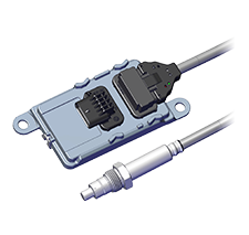
The automobile wheel speed sensor is a subsystem of ABS/ESP, which is used to detect the follow-up signal of wheel speed, convert it into an electrical signal through the Hall effect, and transmit it to the ECU. The ECU judges the speed according to the change characteristics of the electrical signal, so as to regulate the timely work of ABS/ESP.
When Hall element is used as the wheel speed sensor of an automobile, magnetic induction intensity B is usually used as the input signal. When magnetic induction intensity B changes with target wheel rotation, Hall current pulse is generated. After amplification, filtration and power amplifier by Hall integrated circuit, current pulse sequence is output outward, and its frequency changes with the rotation speed of the target wheel.
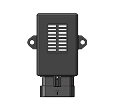
Customized to customer choice of connection system.
Custom packaging can be provided to meet any need, please contact KESENS Engineering for details.

-
Tel: 0573-82858999Fax: 0573-82672893
-
Email: info@kesens.comAddress: No. 199, Tianshu Road, Economic and Technological Development Zone, Jiaxing City, Zhejiang Province,China.
-